RFID x NFC
Nos dias atuais tem se tornado comum o uso da identificação por radiofrequência / Radio Frequency Identification (RFID). Como por exemplo podemos citar crachás em empresas, cartões de pagamento (ex. cartão de débito), cartões de transporte públicos (ex. cartão de metro, ônibus, etc), Tags para estacionamento e praças de pedágios, entre muitos outros exemplos onde podemos aplicar.
Nos últimos anos, um novo termo começou a expandir-se em conexão com RFID: comunicação de campo próximo / Near Field Communication (NFC).
O RFID e o NFC são muitas vezes confundidos, mas definitivamente não são os mesmos.
Embora os leitores NFC possam ler e escrever em algumas tags RFID, a NFC possui mais capacidades do que RFID e permite uma maior variedade de usos. Você pode pensar em NFC como uma extensão da RFID, com base em alguns dos muitos padrões RFID para criar uma plataforma de troca de dados mais ampla.
O que é RFID?
Imagine que você está sentado na sua varanda à noite. Você liga a luz da varanda, e você pode ver seu vizinho quando ele passa perto de sua casa porque a luz reflete nele e você pode observar.
Isso é RFID passivo. O sinal de rádio de um leitor RFID passivo atinge uma etiqueta, a etiqueta absorve a energia e “reflete” sua identidade.
Agora imagine que você acenda a luz da sua varanda, e seu vizinho vê isso e acende a luz da varanda da casa dele para que você possa vê-lo acenando de sua varanda.
Isso é RFID ativo. O RFID ativo pode suportar um alcance mais longo, porque o receptor possui sua própria fonte de energia e, portanto, pode gerar seu próprio sinal de rádio em vez de depender da energia que absorve do remetente (RFID passivo).
O RFID é muito parecido com as duas varandas utilizadas nos exemplos anteriores. Você e seu vizinho se conhecem, sabem os rostos uns dos outros, mas você realmente não sabe muito além disso sobre ele. Você não troca mensagens significativas.
RFID não é uma tecnologia de comunicação. Em vez disso, é uma tecnologia projetada para identificação. As etiquetas RFID podem conter uma pequena quantidade de dados e você pode ler e escrever a partir de leitores de RFID, mas a quantidade de dados de que é falada é trivial.
O que é NFC?
Agora imagine que outro vizinho passe perto da sua varanda, e quando você o vê, você acaba convidando ele para a sua varanda para conversarem. Ele aceita seu convite, e você se senta junto, troca informações sobre as vidas de ambos e desenvolvem um relacionamento. Vocês se falam um com o outro e vocês se escutam durante alguns minutos. Isso é NFC.
A tecnologia NFC foi projetada para desenvolver a RFID, permitindo trocas mais complexas entre os participantes. O NFC também permite que você escreva dados para certos tipos de etiquetas RFID usando um formato padrão, independente do tipo de tag. Também é possível se comunicar com outros dispositivos NFC em uma troca bidirecional ou duplex.
Os dispositivos NFC podem trocar informações sobre os recursos uns dos outros, trocar registros e informações.
Continua…
Setting up RTL-SDR on Raspberry Pi 3
This post presents the RTL-SDR setup on Raspberry Pi 3 with Raspbian

Setting up the environment
Open the terminal, then:
pi@raspberrypi:~ $ sudo apt-get install gnuradio % take some time to install all packages
pi@raspberrypi:~ $ gnuradio-companion % if it opens the gnuradio-companion, everything is ok
Installing RTL-SDR and gr-osmosdr packages
pi@raspberrypi:~ $ sudo apt-get install rtl-sdr gr-osmosdr
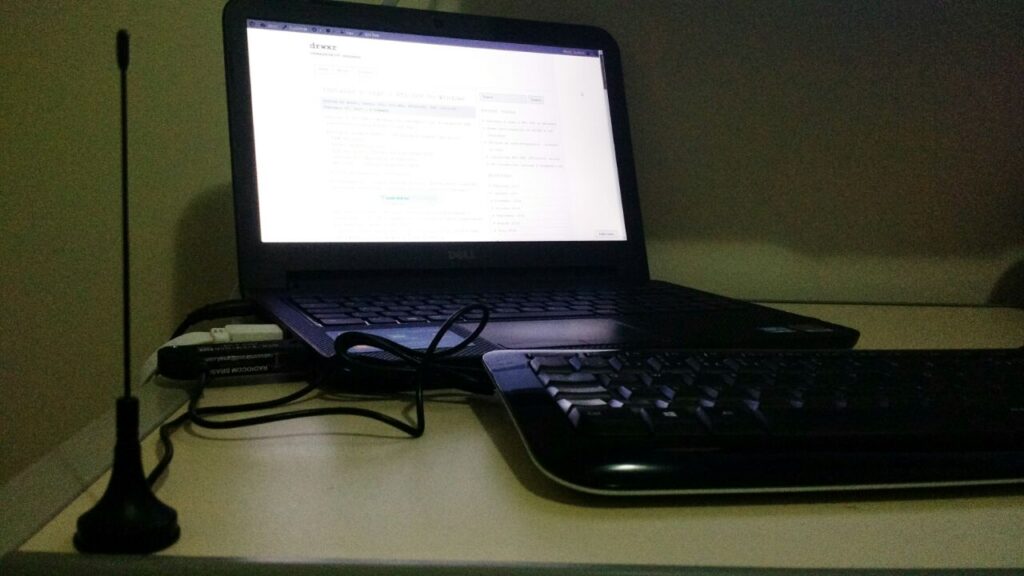
After successfully installing the packages, plug the RTL-SDR to the Raspberry Pi 3 USB Port, then list the USB devices connected to the Raspberry Pi 3:
pi@raspberrypi:~ $ lsusb
Look for Realtek device (RTL), in my case “Realtek Semiconductor Corp. RTL2838 DVB-T”:

Now it is time to check if RTL-SDR is working:

In my case it is working by the first time on Raspberry Pi 3, but there is a known issue (on Ubuntu) related to driver conflict (it uses the Digital TV Driver – dvb_usb_rtl28xxu), if this is your case, do the following:
pi@raspberrypi:~ $ sudo rmmod dvb_usb_rtl28xxu % to make this fix permanent, you have to move driver dvb_usb_rtl28xxu to blacklist
and, try again:
pi@raspberrypi:~ $ rtl_test
Testing time 🙂
Install the GQRX, through apt-get:
pi@raspberrypi:~ $ sudo apt-get install gqrx-sdr
Then run GQRX:
pi@raspberrypi:~ $ gqrx
If not asked to select I/O Device, go to “File” > “I/O Devices” then select Realtek RTL-SDR, now you can click “Power” button then you can hear noise and see FFT live graph (up) and waterfall live graph (bottom).
Pay attention:
Due to processing limitations from Raspberry Pi, to avoid crashes, you have to reduce the sample rate for GQRX, to do it go to: “File” > “I/O Devices” > “Sample Rate” or edit /home/pi/.config/gqrx/default.conf
RTL-SDR known to works up to 2.4 Msps on Raspberry Pi 3 and up to 1.44 Msps on Raspberry Pi 2.
In most cases you can reduce the CPU load further by reducing the window size, sample rate, FFT rate and FFT size (try 2048 at 10-15 Hz). If you are only interested in the FFT, set Mode to “Demod Off”. This will greatly reduce the CPU load.

Another option due to GQRX limitation on Raspberry Pi, you could try QTCSDR on GitHub that also allows TX through GPIO 18 (rpitx), but now just to check RX function:
- git clone https://github.com/ha7ilm/qtcsdr
- cd qtcsdr
- ./rpi-install.sh
- ./rpi-test.sh
If rpi-test.sh succeeds, then type qtcsdr on command line.
pi@raspberrypi:~ $ qtcsdr

Congratulations, your RTL-SDR is working on Raspberry Pi 3! Now you can use available SDR tools on Raspberry Pi 3.
“Underlining” problems of software implementation
Today, when considering security aspects, there are many different techniques to implement software and systems, most of them focus on implementation and test/verification. Majority of research in this area is related to develop new tools to check the integrity of the software later, during the verification phase.
To understand design phases that this post considers as baseline, considers the following systems life cycle phases:

This post introduces a life cycle phase that can be called as conceptual phase. The conceptual phase sometimes is “neglected” due to misunderstood and normally including excuses related to restrictions such as cost, time, and limited resources (summarized as “wasting time” with a conceptual phase).
In IT business, this consideration of time is more crucial because technology evolution has a high pace and launching solutions to market is crucial to survive and guarantee a market share and right time to market.
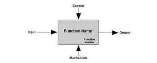
To support this conceptual phase, we presents a tool called “IDEF0” to give an example and illustrated the importance of knowing everything that interacts with your system or function. The objective is to provide an early knowledge about your System of Interest anticipating events, states and conditions that will emerges during implementation phase or even worst, during operation phase (after deploy, during users usage).
First step is to understand that the system that you will implement has interfaces to others (e.g. users, systems, environment, etc.) requiring inputs, processing these inputs (function/system objective) and providing outputs which are subjected, during “processing”, to controls and mechanism entities (e.g. power, statuses, etc.) so your system is no more a lonely entity and you anticipate stakeholders that interacts to your system and what is normally expected from them.
Now, your system has a set of interfaces that you need to understand and so, create a set of requirements that met these interfaces (what it shall accomplish). At this point, when you need to understand the users or other systems’ needs, we bring a concept that help you develop better systems, this concept is called, Systems Thinking.
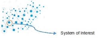
Systems thinking is a capability of developer to view all entities that comprise the system or where it is part of (holistic approach), with System being a set of parts that relate to each other. The most important element in a system view – and sometimes neglected – is the relations among these entities.
With the tool presented and in this conceptual phase it is essential to have an abstraction level of your architecture to understand and identify all the relations of your System of Interest, which is your system under analysis. This abstraction level requires an approach that avoids the implementation decisions (e.g., it will run a specific Operating System) and thinking just about functions and exchanges between entities and stakeholders (e.g. data, energy).
The interface map and correlation of functions empowers developers with the capability to create scenarios that the system will operate and understand the possible threats that can emerge from these scenarios (e.g. if system lose specific input).
After this initial analysis, you have a list of your system functions (it shall comply), you have a map of your systems interfaces and you have concepts of operation (or scenarios) for your system (e.g. normal operation, power interruption). With these information, and considering the security aspects you are able to conduct a preliminary security assessment; anticipating cases or flaws prior to implementation or deploy, reducing future fixes (costly).
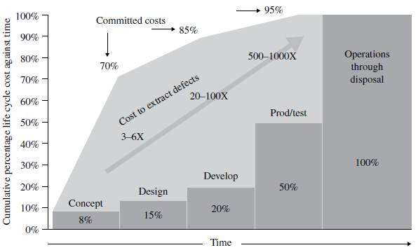
During the conceptual phase analysis, you design the system in a high abstraction level allowing early analysis and deriving requirements and constraints that your system requires (e.g. input values – string with X characters – avoiding buffer overflows).
After, it is possible to proceed to the next phase, implementation, where the “code” is developed considering these requirements and constraints raised during conceptual phase that complements the initial objectives. This approach can also be called as Requirements Driven, although this term is very common during software development environment, in general, it is not regarding the entire lifecycle or as proposed during a conceptual analysis in a higher abstraction layer.
An interesting case about architectural security is related to Redis (read more at http://antirez.com/news/96)
Conclusion,
There are problems related to security that cannot be classified as an implementation issue (e.g. flaws) but a bad requirement specification or lack of it, like environment and operational considerations/analysis. Therefore, it could be anticipated with a conceptual phase analysis, which would lead to the development of a more resilient architecture.
This is a simple view of the importance that must be given to a conceptual phase and consequently requirements definitions when developing a system or implementing a code. I hope that this post may be useful to open your mind and if you have, some questions contact us to clarify the concepts and the perspective about this subject.
Instalar e usar o RTL-SDR no Windows
Para uso do RTL-SDR no Windows, recomendamos o uso de um pacote SDR disponibilizado pela Airspy (clique aqui)
Neste post estamos usando o “SDR Software Package” que inclui:
– SDR# rev 1500
– Airspy Calibration Tool
– ADSB Spy rev 37 (Decodificador de sinais ADSB)
– Spectrum Spy (Analisador de Espectro)
– Astro.Spy – Utilitário para astronomia
Se desejar, baixe aqui: sdrsharp-x86
Ao descompactar o arquivo sdrsharp-x86.zip, deve-se estar conectado na internet e executar o seguinte arquivo (install-rtlsdr.bat):

Este arquivo irá se conectar ao servidor da OSMOCOM e baixar o driver para o RTL-SDR e também fará o download do Zadig, responsável por instalar o driver do RTL-SDR.
* Neste instante, plugue seu dongle do RTL-SDR e não instale nada que o Windows venha a propor de forma automática.
Na pasta criada a partir do sdrsharp-x86.zip, execute o arquivo zadig.exe como administrador:

Dentro do Zadig, selecione no menu Options > List All Devices de forma a deixar a opção selecionada:

Conforme exemplo acima, ele já encontrou 6 dispositivos (vide barra inferior).
* Neste caso, o Zadig já encontrou o driver referente ao RTL-SDR, na figura abaixo como “RTL2838UHIDIR”, no entanto, conforme Quick Start Guide usado de referência, pode ser o caso que o driver não faça referência direta ao RTL e pode aparecer algo como “Bulk-In, Interface (Interface 0)”.
Garanta que a seta esteja apontando para WinUSB e clique em “Replace Driver”


Em seguida podemos verificar (na pasta criada a partir do sdrsharp-x86.zip) os seguintes aplicativos já mencionados:

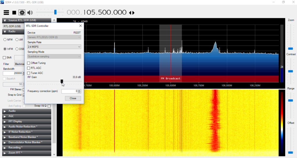
Execute o SDRSharp.exe e já defina como “Source” o RTL-SDR (USB):

Em seguida clique em “Play” e o SDR# já irá iniciar a captura:

* Importante! Lembrar de ajustar o ganho RF. Um ganho de “zero” só irá captar sinais muito forte por isso é necessário ajustar o ganho até aparecer o sinal desejado (no exemplo acima nenhum sinal está sendo captado). Para ajustar o ganho, clique em configurações e em seguida ajuste o “RF Gain”:

A partir de agora, seu RTL-SDR está configurado no Windows! Agora é procurar projetos para praticar e começar a fuçar com o RTL-SDR.
Qualquer dúvida, use o espaço de perguntas ou entre em contato.
* Post elaborado usando o Windows 10
drwxr participation on MITRE’s IoT Challenge

So, it is over the MITRE’s IoT Challenge and unfortunately we did not won the challenge (we got #5 out of 130 teams worldwide – check leaderboard). This challenge was launched on October 2016 until January 2017.
Despite the challenge’s result, it was a great opportunity to get involved in a real case related to IoT and Security, the main problem to be solved can be summarized as MITRE’s words:
We are looking for a unique identifier or fingerprint to enable administrators to enumerate the IoT devices while passively observing the network
And the challenge working as:
Each registered team was given access to radio frequency (RF) capture data from the model home network. The first recording was a baseline RF capture of the environment. The second recording was a “challenge” RF recording in which IoT devices were added, removed, or modified. Each team needed to answer a series of questions about the baseline and challenge recordings, which allowed MITRE to assess the team’s ability to uniquely identify devices.

So after this challenge, we improved our knowledge on IoT Protocols, GNU Radio usage, scapy-radio and methods to identify devices. Based on our status after challenge end, we will continue researching methods to identify IoT devices using data provided by MITRE, so we hope to share our findings on this area soon.
References: