Installing RTL-SDR (RTL2832U) driver
This content is a piece of our initiative to explain how to start your studies with RTL-SDR.
In this post we’ll explain about how to install the rtl-sdr driver.
To install the RTL-SDR device on a Linux computer is relatively quick and easy.
These instructions are designed to run on Linux distributions based on Debian or Ubuntu.
Installing the drivers:
1. Open the terminal and make sure you are in the home directory.
2. Update your Linux distribution:
sudo apt-get update
3. Install the necessary tools such as: git, cmake, build-essential
sudo apt-get install git
sudo apt-get install cmake
sudo apt-get install build-essential
4. Install the library called “libusb-1.0-0-dev” which provides access to USB devices.
sudo apt-get install libusb-1.0-0-dev
5. Download and install the RTL2832U from vendor site:
git clone git://git.osmocom.org/rtl-sdr.git
cd rtl-sdr/
mkdir build
cd build
cmake ../ -DINSTALL_UDEV_RULES=ON
make
sudo make install
sudo ldconfig
sudo cp ../rtl-sdr.rules /etc/udev/rules.d/
6. Create a “blacklist” to the default driver which loads automatically using the RTL-SDR device as a TV receiver, because this isn’t the functionality we want to use (tv receiver).
A. Access as administrator the directory: /etc/modprobe.d
B. Create a new file called “blacklist-rtl.conf” and add the following line in the file:
blacklist dvb_usb_rtl28xxu
blacklist rtl2832
blacklist rtl2830
C. Save the file and reboot the machine.
7. After reboot the machine, test if the device is actually running. To test type the follow command in the terminal:
rtl_test -t
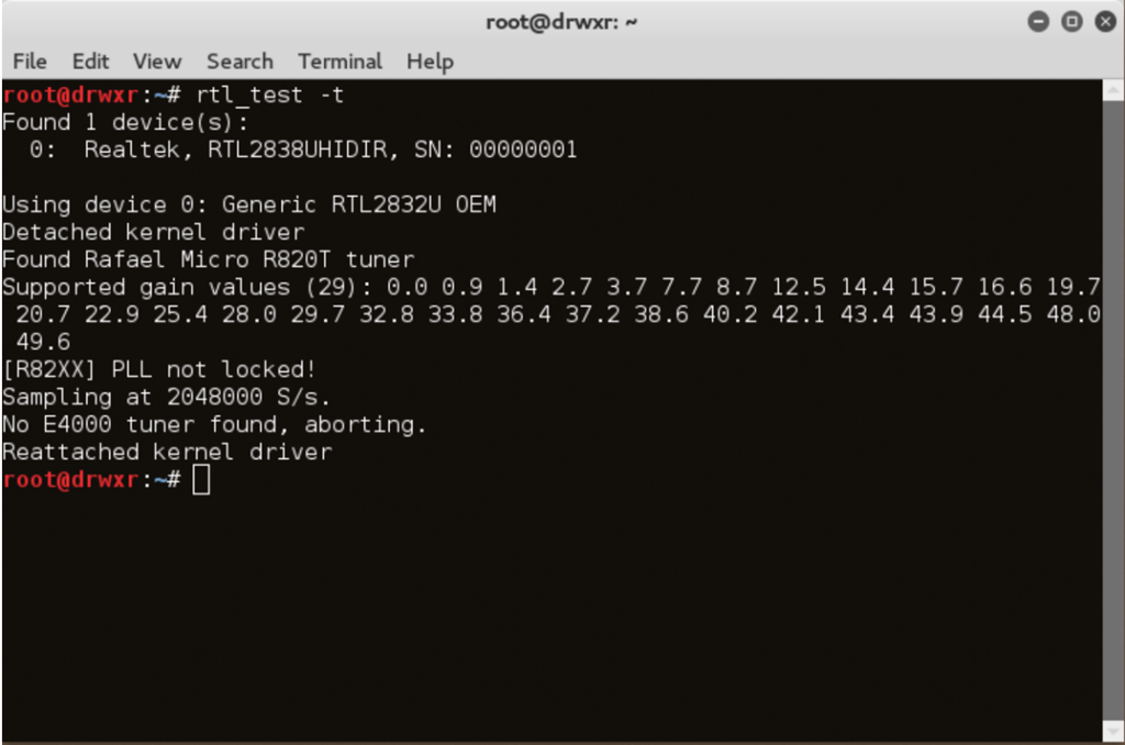
Don’t worry with the follow messages:
“PLL not locked”
“No E4000 tuner found, aborting”.
If you see these messages above it is a sign that your driver and your device is working properly and you are ready to install some applications like GQRX, Dump1090, CubicSDR and others…
FM transmitter through a Raspberry pi
In this post we’ll turn the Raspberry Pi into an FM transmitter in a few steps.
ATTENTION: remember that in some countries the radio transmissions of any kind are subject to federal laws and regulations.
This is a simple and very interesting article.
To turn your raspberry pi in FM transmitter we will use the rpitx of F5OEO (https://github.com/F5OEO/rpitx) , rpitx is a radio transmitter for Raspberry Pi (B, B+, PI2, PI3 and PI zero) that transmits RF directly to GPIO. It can handle frequencies from 5 KHz up to 500 MHz.
For installing do the following:
git clone https://github.com/F5OEO/rpitx
cd ./rpitx
sudo ./install.sh
The install script (install.sh) will download and install all the needed dependencies. This takes a while.
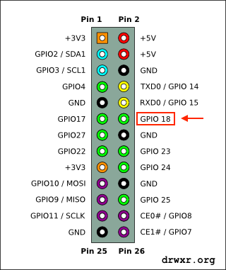
We gonna connect a ~20cm or so plain wire to GPIO 18 (which is pin 12 on header P2) to act as an antenna, and tune an FM radio.
The optimal length of the wire depends the frequency you will want to transmit.
GPIO pins (General Purpose Input/Output) are ports (pins) programmable that can be used to input and/or output data. They are mainly used to communicate with external devices like microcontroller or microprocessor.

In this article we going to transmit FM, so we gonna use the pifm.
Pifm converts an audio file (Wav, 48KHz, 1 channel, pcm_s16le codec) to Narrow band FM (12.5khz excursion) and outputs it to a .ft file. Assuming your audio file is in your current working directory.
./pifm gunsnroses.wav fm.ft
Then after execute the command that created the fm.ft, lets execute the command bellow that will transmit the audio at 92.0MHz (you can change).
sudo ./rpitx -m RF -i fm.ft -f 92000 -l
Video:
Automatic Dependent Surveillance-Broadcast – ADS-B (Part I)
This content is a piece of our initiative to study security in aviation. All experiences and content developed by us will be available here on right moment. To start, we will understand a little about ADS-B.
ADS-B is one of technologies from NextGen Platform (Next Generation Air Transportation). NextGen is a initiative from FAA (Federal Aviation Administration) for enhance the current Air Traffic Control. The proposal promises a great operational gains, security and financial support for the entire chain of stakeholders involved in air transportation.
ADS-B technology is responsible for communication between aircrafts and between aircraft and air traffic control. This technology has been widely used in aircrafts and it will be mandatory adoption in the coming years (from 2020 US / Europe 2017).
This is a cooperative surveillance technology for tracking aircraft. Each aircraft determine your position via GPS. Every aircraft equipped with ADS-B will periodically send your location information, speed, altitude, identification and other details to ground stations and others aircrafts also equipped with ADS-B present in that area.
This technology will replace the radar as the primary method of surveillance to detect the position of aircraft worldwide.
Supposedly the ADS-B technology should increase safety in aviation by making visible aircraft in real time, exchanging information such as position and velocity, transmitted every second, but the current technology of ADS-B make use of broadcast transmission, in clear text ( without encryption or other security measures) using radio frequency (1090MHz – Modulation PPM).
ADS-B technology consists of two different systems that are ADS-B In and Out.
ADS-B Out
It is the basic level of ADS-B functionality. It’s basically all communication that is issued by the ADS-B aircraft.
ADS-B IN
The information reported by ADS-B Out (other aircraft) will be received by aircraft equipped with ADS-B In system. This functionality is intended to alert the crew about the traffic around you.
Understood the basics, let’s look under security optical…
First, we have the situation where the plane is sending uncontrolled information concerning that flight. This set of information is sent in broadcast, or for everyone. It does not require authentication and is not made any kind of control of the recipient and sender.
The signal sent by the ADS-B uses the 1090MHz frequency modulation Digital Pulse Position modulation (PPM) and Manchester code where a ZERO bit is encoded 01 and the ONE bit is encoded 10.
An ADS-B message contains 112 bits, for example:
Example message in BINARY format:
10001101010010000100000011010110001000000010110011000011
01110001110000110010110011100000010101110110000010011000
The same example in HEX format:
8D4840D6202CC371C32CE0576098
The table below shows the bit organization of the message.
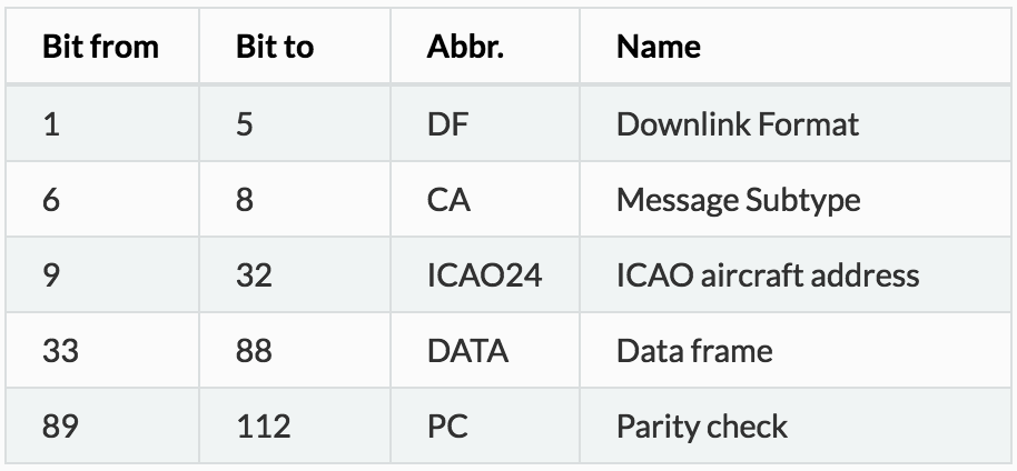
In a future opportunity we will detail every message part….
So far we understood that ADS-B from every airplane will be emitting the bit sequence shown above approximately 2 times per second.
Sites like FlightRadar and FlightAware uses radio receivers around the world, collaboratively, to capture the ADS-B information of the aircrafts and centered in a friendly way on the map showing the vast majority of flights flown in the world.
Illustrating how the tracking sites of ADS-B aircraft:

The ADS-B waveform can be observed in following images:
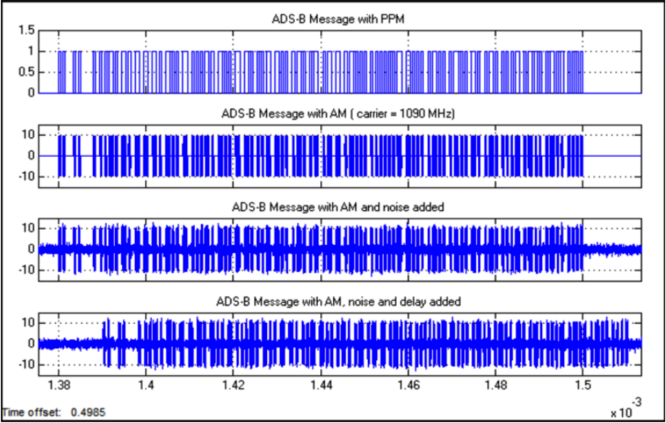

This is the first content, introduction to ADS-B technology. In the next content we will discuss more about the decoding and show how you can capture the information of the aircraft in its viewing area. Only after that we can have a view of the risks of ADS-B technology…
Think how dangerous a Replay Attack could be in aviation scenario.
to be continued…
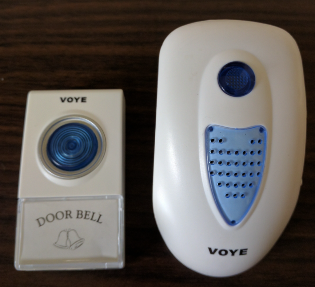
Replay Attack – Doorbell
Recently I bought a low cost wireless doorbell so I decided to analyse the RF communication and reproduce a replay attack.
To accomplish the attack I used an Ettus USRP2 N210 SDR (Software Defined Radio), a Voye wireless doorbell and GNU Radio.
The replay attack (also called as playback attack) is simple and very interesting attack, it works by simply recording a signal and then rebroadcasting it once it used a “fix code” signal to activate the doorbell.

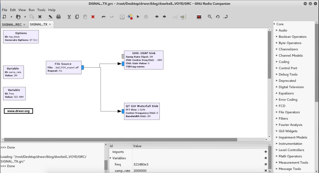
GNU Radio
GNU Radio Companion (GRC) is a graphical tool for creating signal flow graphs and generating flow-graph source code.
More info: http://gnuradio.org/redmine/projects/gnuradio/wiki/GNURadioCompanion
Identifying the signal
Usually doorbells operates at frequencies of 433Mhz (Europe) or 315Mhz (America), it was first noticed the frequency of 433Mhz in order to get signal but nothing was found. Analyzing the 315MHz frequency we found the signal from the doorbell transmitter.
We used GQRX to clearly identify the frequency:

Capturing the signal
We recorded the signal from the doorbell transmitter in GNU Radio into a RAW file.
We’re using 2e6 (2M) as Sample Rate and this value should be used in every step.

Opening this up in AUDACITY we can see groups of pulses making up a single button press and we can identify this is a OOK (On-Off Keying) Signal.

On zooming in to a button press, we can see these button presses are made up of similar looking groups.

Notice that we’ve exported 4 sequences because the receiver has a error rate and it needs to receive more than 1 package of bits.
We gonna export using the following configuration:

Transmitting the signal
Finally, the last step was to create a flow graph to transmit the raw signal isolated.
After executing the doorbell will ring…
Video of replay attack:
Captando sinais Infravermelhos (IR) com RTL
Neste artigo será apresentado como utilizar o RTL para receber sinais de controle remoto infravermelho (IR), incluindo o controle fornecido com o equipamento RTL. O receptor infravermelho do RTL é surpreendentemente poderoso, ele foi capaz de captar sinais de todos os controles remotos que testamos, retornando os dados brutos (raw) para decodificação.
É possível criar um replicador ou emissor de infravermelho bastante simples, o mais complexo é encontrar o que deve ser transmitido. Vamos tratar aqui de leitura raw, ou seja do que os controles IR enviam. Neste momento não será demonstrado como replicar ou como construir um emissor IR.
O RTL-SDR é um receptor de TV Digital via conexão USB para Computador, que pode ser utilizado também como Rádio para captar Ondas Eletromagnéticas.
Geralmente estes receptores contém uma antena e um controle remoto infravermelho (IR), que é utilizado para ligar/desligar, mudar de canais, configurações de volume, etc.
Isso quer dizer que o equipamento contém um receptor de Infravermelho (IR), além do receptor de rádio frequência da TV digital.

(Receptor RTL)

(Receptor Infravermelho)
Espectro de frequências
O RTL que utilizamos (Realtek RTL2838 DBV-T) pode sintonizar dentro de 24 MHz – 1.7 GHz, ou seja 2.4 x 10⁷ Hz até 1.7×10⁹ Hz.
Abaixo o espectro de frequência completo:

(Espectro de frequência)
Em frequências mais altas, ou comprimentos de onda mais curtos, temos a luz infravermelha visível, ultravioleta, entre outras.
A radiação infravermelha é uma radiação eletromagnética cujo comprimento de onda é maior do que o da luz visível, e por consequência não é visível para os seres humanos. O nome significa “abaixo do vermelho” (do latim infra, “abaixo”). Isto se deve ao fato de a cor vermelha possuir a menor frequência do espectro de luz visível e o infravermelho possuir uma frequência logo abaixo da dele.
O comprimento de onda do infravermelho possui tamanho aproximadamente de 750 nm a 1mm. Estes comprimentos de onda estão muito além da faixa de frequência de sintonizador de a RTL-SDR ou qualquer SDR comum.
O sensor infravermelho, que é um componente separado do adaptador RTL-SDR, pode receber esses sinais.
RTL_IR
Existe uma ferramenta, que faz parte de uma lib específica, chamada librtlsdr, a qual contém alguns códigos para trabalhar com os receptores do dispositivo RTL. A princípio estas ferramentas foram criadas para trabalho com o receptor Rafael Micro R820T (ou similares, que recebem 24 MHz – 1.7 GHz). Recentemente foi incorporado ao repositório arquivos que possibilitam a captação de infravermelho do dispositivo (rlt_ir).
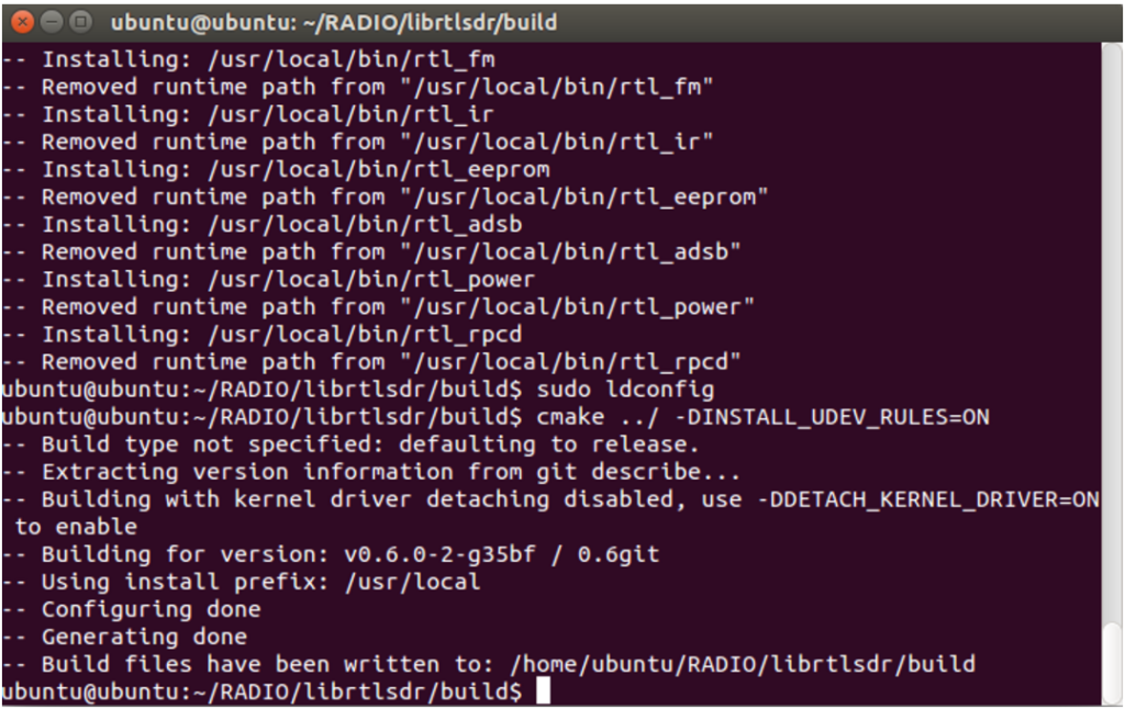
Comandos para instalação
Abaixo um breve tutorial para realizar a instalação:
git clone https://github.com/librtlsdr/librtlsdr.git
cd librtlsdr
mkdir build
cd build
cmake ../
make
sudo make install
sudo ldconfig
Para que usuários normais (sem privilégios de root) possam utilizar, deve ser executado também a instrução abaixo:
cmake ../ -DINSTALL_UDEV_RULES=ON
Utilização
Após a instalação, tudo estará preparado para receber as informações. Para deixar o dispositivo em modo “ouvinte” deve ser executado o seguinte comando:
rtl_ir
Executando o comando rtl_ir, deverá aparecer a seguinte mensagem:

Isso indica que o processo funcionou e o dispositivo está pronto para receber os dados.
Para testar, basta apontar um controle infravermelho (televisão, TV a cabo, etc) e apertar as teclas.
Os bits enviados pelo controle infravermelho, serão apresentados na tela, conforme imagem abaixo:

Conclusão
Como pode ser visto acima, é possível obter facilmente informações dos controles infravermelho, ou seja é apenas uma atividade introdutória ao assunto, podendo ser explorada muito mais a fundo, como por exemplo decodificação e replicação de sinais, entre outras coisas.